Update: I have put this project on Google Code including source code. It can be found at https://code.google.com/p/logicgatesimulator/.
Update Update:Since Google is deprecating Google Code I have migrated the project over to github. It can now be found at https://github.com/kokuda/logicgatesimulator
I recently resurrected a C# project I was working on some time ago that I had almost forgotten. I was reminded, again, of a computer game I used to play in school called “Rocky’s Boots“. The last time I thought of it I decided to make a framework for building something like it in C#. This time I was reminded that I had already built it. Fortunately, I was able to find it.
The game was one where you connect components together to “kick” blocks of certain shapes and colours. I didn’t realize until I was much older that those components were basic logic gates and we were essentially programming our “kicker”.
To that end I built a tool in C# for connecting basic components together to form complicated circuits. It has the basic AND,OR,NOT and a few other gates along with wires to connect their inputs and outputs. The circuits can be saved out to files, and loaded in as individual components which can be duplicated and further connected to make more complex circuits. There is no kicking, nor is there any game to this, it is just the simulator, but it is fun to build circuits that do something.
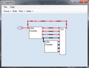
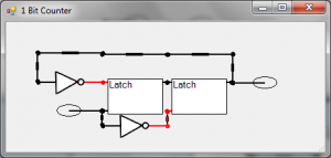
Using those components I have built other things like NOR, XOR and Latches and gone so far as to build an 8 bit counter, using 2x4bit counters which are made of 4x1bit counters
which are made with latches for storage which are made with SR Flip Flops – all built out of AND,NAND,NOT,OR.
There is no documentation yet so… here is the documentation:
- New items are added to the top left of the working area – move them by clicking and dragging
- Power items can be either ON or Strobing on and off.
- Bulbs just glow red when powered.
- The inputs are generally on the left side of each item, with the exception of things like the “Display” items that have a latch input in the top right corner (they will only update their display when this is set).
- You can save and load circuits that you have made
- You can create new user defined “Gates” by saving a circuit with at least one input and one output and importing it under the “
Gates->User Defined...” tool. Inputs are defined by Power sources and outputs are defined by Bulbs. Load some of the examples, likecomponents\NOT.xmlfor examples of user-defined components.
Here is the application. Some of the sample files are included with it that you should be able to load.
Perhaps I will make this open source at some point. I see no reason not to give away the source, but it isn’t quite ready for prime time yet. I would like to make the core components plugin-able – perhaps even being written in an interpreted language – to allow some unique components without rewriting the application.


Pingback: alex
Dear Pocois
is it possible to mail me the source code?
thank you
Dear Pocois.
Thank for your project. When i try to build your project then i getting following error is:
“Cannot import the following key file: . The key file may be password protected. To correct this, try to import the certificate again or import the certificate manually into the current user’s personal certificate store. LogicSim ”
Can you help me resolve this error.
Thank